EPAC will provide a step-change in capabilities for laser-driven accelerator research in the UK, enabling a plasma wakefield accelerator facility with multi-GeV electron beams and spatially coherent x-ray and gamma-ray beams for cutting-edge experiments in plasma physics, laboratory astrophysics and condensed matter and material science.
The versatile experimental areas in EPAC can drive high-energy protons, ions, neutrons and muons by merely changing the target geometry, enabling multi-modal capability for probing highly dynamic processes in for example nature or industrial components. The unique capabilities of EPAC, combining near-light speed particles and synchronised ultra-intense electromagnetic fields, would provide a world-leading platform capable of generating extreme states of matter and the tools to probe, control and manipulate them, enabling exploration of some key fundamental questions in nature including those in quantum electrodynamics.
There is also potential impact on long term fundamental science programmes, such as the future technical basis of particle physics accelerators, that will likely require this sort of disruptive approach to accelerator science.
EPAC draws many similarities to our current Gemini Laser system. However, EPAC will run at a faster rate of 10 Hz thanks to technology developed on our DiPOLE Laser system, allowing scientists to build better statistics.
Key scientific experiments on EPAC will include: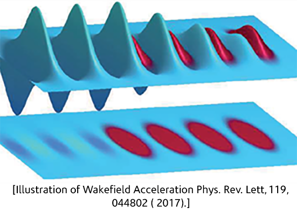
- Driving fundamental science into advanced accelerators
- Laboratory astro-physics
- Quantum electrodynamics experiments
Advanced Imaging Techniques:
- Imaging low density materials at high resolution (e.g. Fluids, carbon-based components ).
- Imaging large dense objects at high resolution in 3D (e.g. micron-scale cracks).
- Imaging dynamics (e.g. crack propagation).
- There is a need for high-flux, high-resolution, compact imaging sources.
- Multi-modal imaging for complementary information.
[Dynamic image capture with short pulse exposure (no magnification, detector resolution ~ 0.1 mm). Single pulse exposure
while the blades rotating at 42,000 rpm.C. M. Brenner et al, PPCF, 58 014039, (2015)]
EPAC's imaging techniques will be based on phase contrast, not shadow:
Absorption-based imaging:
- Contrast through photon attenuation – good for metals.
- Does not work well for materials with small differences in densities.
Phase contrast enhancement:
- Object deflects photons, sharpens edges of different densities.
- Propagation-based PCI works with polychromatic sources.
- Superior distinction between low Z materials with similar density.
[Image: Laser-driven shock propagating at 7 km/s on microscopic scale. Single-pulse betatron phase-enhanced probing to observe shock break out dynamics and instabilities, and shock-induced stresses/phase transitions.]
Images in header: Image 1: Gemini Laser Facility
Image 2: CALTA DiPOLE Laser Facility